A concrete pump truck is a device that integrates a pumping system for pumping concrete and a boom system for fabrics on a chassis of a vehicle. The pumping system uses the power of the chassis engine to pressurize the concrete in the hopper. Inside the pipe, the pipe is attached to the boom, and the operator controls the movement of the boom to directly send the concrete pumped out by the pumping system to the pouring point.
Basic structure components
General picture of concrete pump truck: 1. Chassis; 2. Boom system; 3. Turret; 4. Hydraulic system; 5. Electrical system; 6. Pumping system
There are many types of concrete pump trucks, but the basic components are the same. Concrete pump trucks are mainly composed of six parts: chassis, boom system, turret, pumping system, hydraulic system and electrical system.
1. The chassis consists of the car chassis, PTO (transfer box) and Fuliang;
2. The boom system consists of a multi-section boom, connecting rod, cylinder and connecting parts.
3. The turret consists of a turntable, a slewing mechanism, a fixed turret (connecting frame) and a supporting structure.
4. The pumping system consists of a pumping mechanism, a hopper, a S-valve assembly, a swinging mechanism, a stirring mechanism, a piping assembly and a boom piping.
5. The hydraulic system is mainly divided into two parts: the pumping hydraulic system and the boom hydraulic system. The pumping hydraulic system includes a main pumping oil circuit system, a distribution valve oil circuit system, a stirring oil circuit system, and a water pump oil circuit system. The boom hydraulic system includes a boom oil system, a leg oil system and a rotary oil system. The hydraulic system is mainly composed of a hydraulic pump, a valve block, an accumulator, a hydraulic motor and other hydraulic components;
6. The electrical system is mainly composed of control cabinets, remote controls and other electrical components.
working principle
After the concrete mixer is discharged to the pump hopper, it is pumped to the delivery pipe by the pumping system and discharged through the end hose (key 15). The unfolding and gathering of the booms is completed by the respective boom cylinders. The elevation angle of the 1# boom (key 7) in the boom can swing from -2° to 90°, and the 2# boom (key 10) and 3# boom (key 12) can swing 180°, four sections. The boom is unfolded in sequence, and the 4# boom (item 14) has the most frequent movements. It can swing about 255°, and the hose at the end should be as close as possible to the casting part, and the boom can be rotated by the motor and decelerated. The machine drives the rotating large bearing to rotate around the fixed turret for 365°.
1—pumping system; 2—legs; 3—pipe assembly; 4—fixed turret; 5—turning table; 6—1# boom cylinder; 7—1# boom; 8—arm rack conveying pipe; —2#Boom cylinder; 10—2# boom; 11—3# boom cylinder; 12—3# boom; 13—4# boom cylinder; 14—4# boom; 15-end hose
|
Type
|
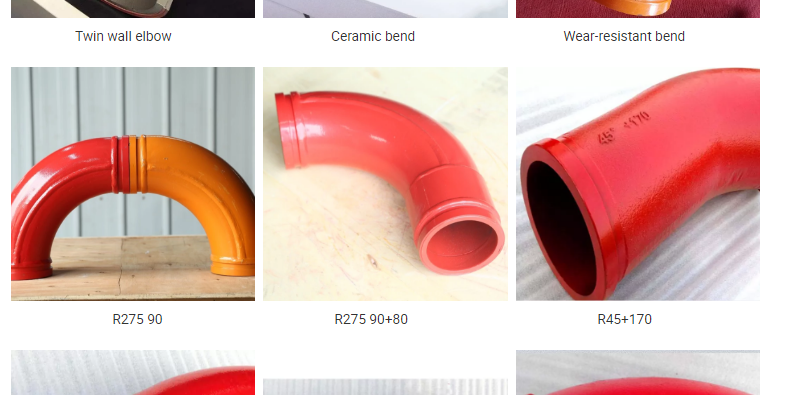
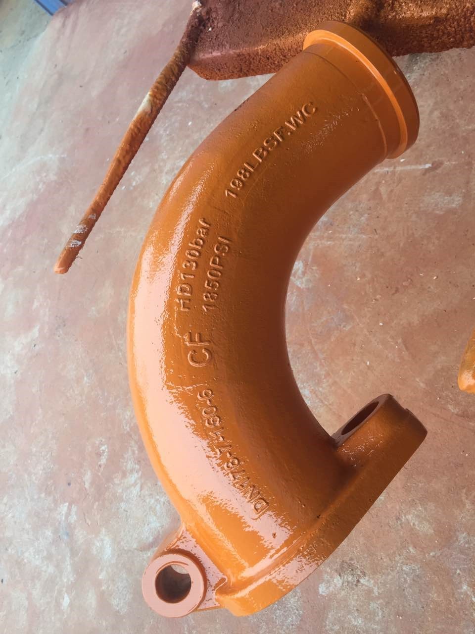
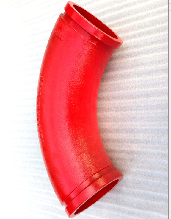
Singe Wall Elbow
|
Double Wall Elbow
|
||||
|
Material
|
Casting Steel, ST52
|
GX350+ST52
|
||||
|
Model
|
DN125
|
DN150
|
DN175
|
DN125
|
DN125
|
|
|
Size
|
R275*90°
|
R275*90°+110mm
|
36°
|
F2000
|
R275*90°
|
R275*90°+110mm
|
|
R275*45°
|
R275*90°+211mm
|
R400*30°
|
A3000
|
R275*45°
|
R275*90°+211mm
|
|
|
R275*25°
|
R275*90°+411mm
|
R400*45°
|
471B
|
R275*25°
|
R275*90°+411mm
|
|
|
R275*20°
|
R275*90°+424mm
|
R400*30°
|
571B
|
R275*20°
|
R275*90°+424mm
|
|
|
R275*15°
|
R275*45°+170mm
|
R488*90°
|
A1000
|
R275*15°
|
R275*45°+170mm
|
|
|
R180*90°
|
R275*45°+310mm
|
R500*90°
|
C1000
|
R180*90°
|
R275*45°+310mm
|
|
|
R232*60°
|
R275*45°+310mm
|
R280*90°
|
B2000
|
R232*60°
|
R275*45°+310mm
|
|
|
R240*36°
|
20°Lengthen
|
R240*36°
|
20°Lengthen
|
|||
|
R240*30°
|
25°+740mm
|
R240*30°
|
25°+740mm
|
|||
|
R240*15°
|
40°Zoomlion
|
R240*15°
|
40°Zoomlion
|
|||
|
R385*29°
|
R385*29°
|
|||||
|
R315*33°
|
R315*33°
|
|||||
|
Forged, Casting
|
||||||
|
Capacity
|
25,000 cubic meters
|
50,000 cubic meters
|
||||
|
Usage
|
For concrete transport in construction work
|
|||||


