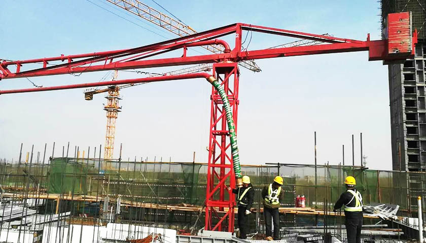
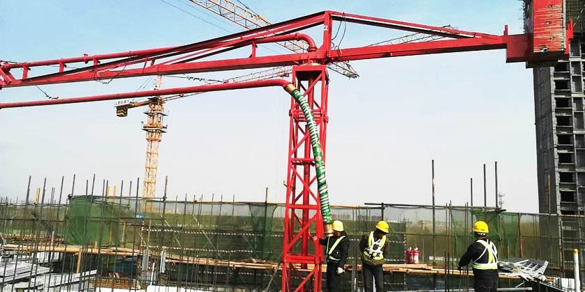
Introduction of Concrete Placing Boom
I Overview
The concrete placing boom, developed and produced by our company, is the auxiliary supporting equipment for the concrete conveying pump. It is connected with the concrete conveying pump through the standard conveying piping, which effectively solves the problems of the wall concrete pouring in the construction site and reduces the labor intensity of workers. It also plays a very important role in providing construction efficiency and reducing accident rates.
Among the concrete placing boom manufacturer in Hebei Province, China, our company has became one of the most professional enterprise which owes a larger scale and the most complete product ranges. And we are also one of the few companies that has passed 9000 certification and environmental assessment.
The concrete placing boom produced by our company adopts a rotary arm-type placing structure and is equipped with a 133mm conveying pipe. The whole machine is manually operated. With stable and reliable structure, light and flexible rotation, 360° Omni-directional forward and backward rotation, the radius of gyration can be arbitrarily adjusted, and the total height of the machine body is appropriate. The placing orientation can be arbitrarily changed by simply pulling the rope. It is the best choice for pouring concrete in construction sites.
II Main Structure of Concrete Placing Boom
Part 1. Main beam frame
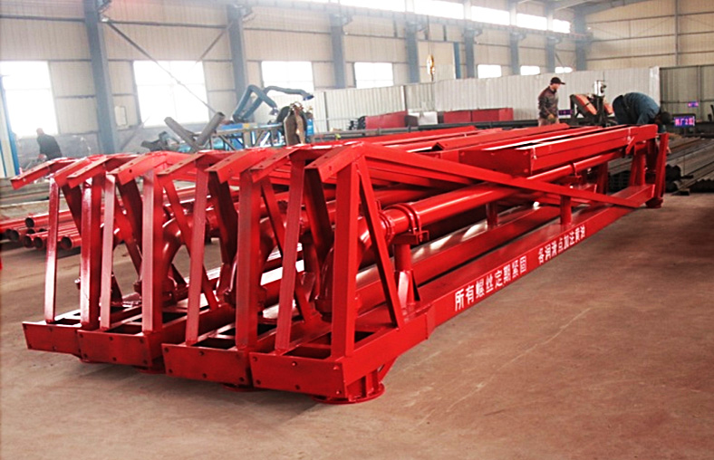
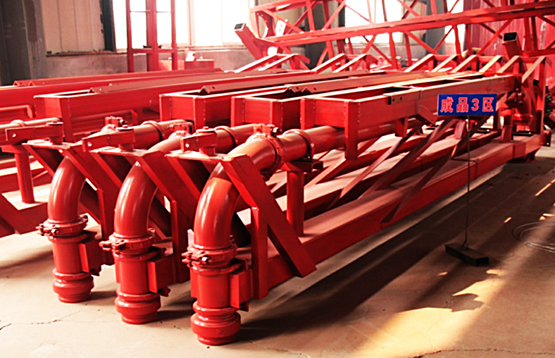
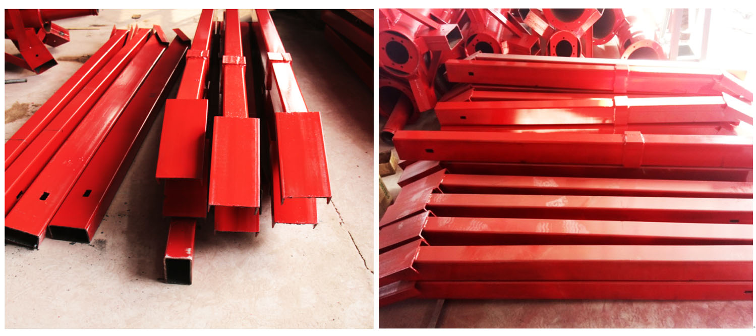
The main girder consists of square steel, angle steel, pipe brackets, pull rods and etc.
The main girder is installed on the slewing bearing seat and can be rotated 360° through the slewing bearing. The front-end of the main girder has a pipe support to fix and support the machine conveying pipe, and the back-end is equipped with a balancer to achieve balance of the counterweight.
Part 2. Stand Frame
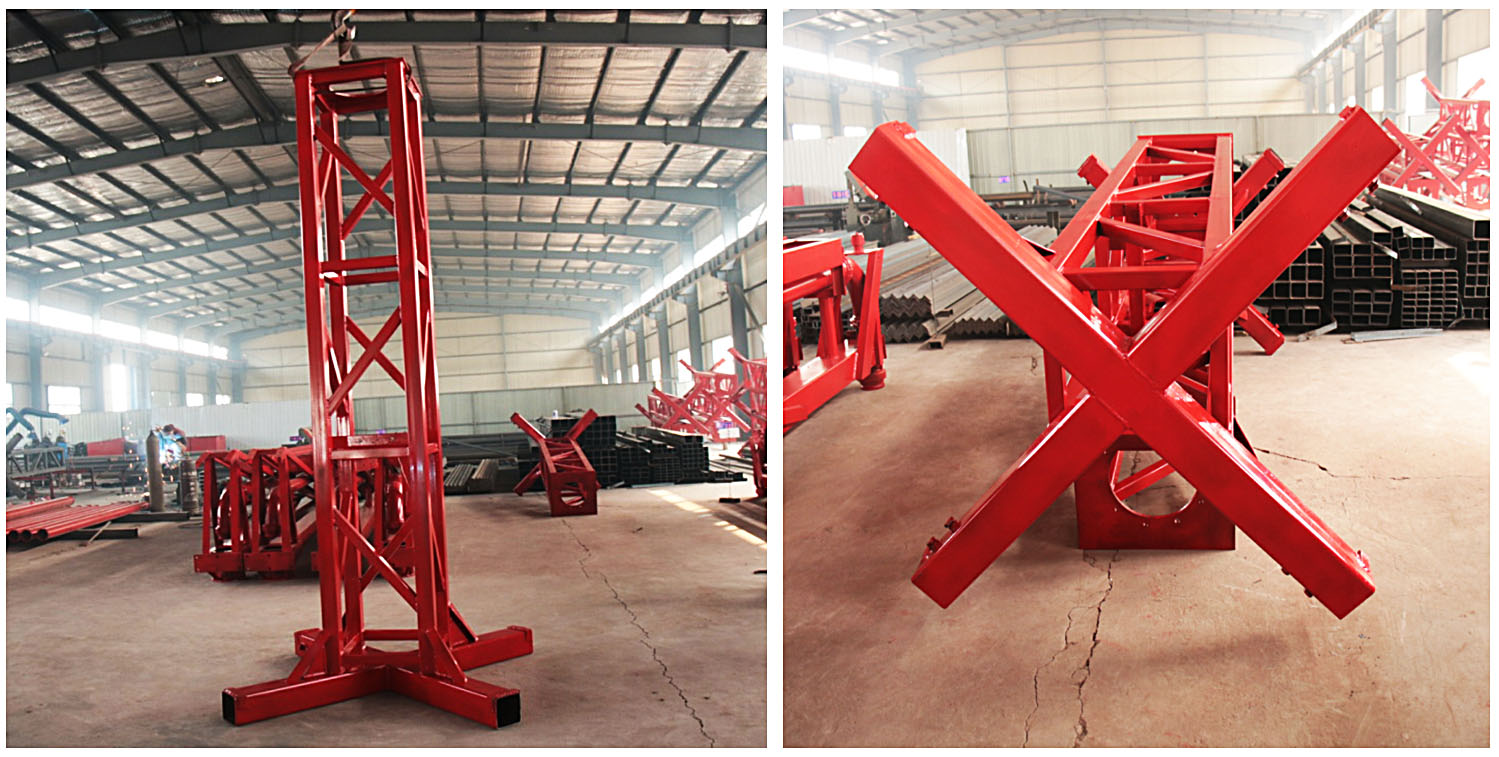
The vertical stand is mainly composed of four legs distributed in a cross shape. The vertical loading of the concrete placing boom acts on the base of its cross-shaped cross section, and is then transmitted to four legs. Each leg has a telescoping leg extending horizontally.
Part 3. Slewing Bearing
The slewing bearing is installed between the upper frame and the support base to connect the slewing bearing.
Part 4. Conveying Pipeline
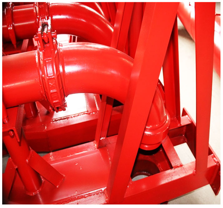
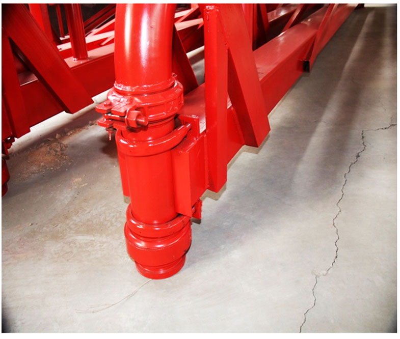
The lower nozzle of the concrete conveying pipe can be arbitrarily extended from the four sides of the machine body. The upper part of the concrete conveying pipe passes through the turning center and goes upwards to the upper frame machine, and then extends to the boom frame at the front end of the upper frame, turning downwards at the front end of the boom frame. The front concrete conveying pipe is relative to the center of rotation of the boom. The pipelines are 90° elbows, vertical pipes, straight bearings, horizontal pipes, elbow bearings, hanging pipes, 45° elbows, end hoses, and pipe clamps.
III Manual Concrete Placing Boom Packing List
| Item. | Specification | Quantity | Unit | Remarks |
| Main beam frame | / | 1 | Pcs | Include the back balancing frame |
| The vertical stand | / | 1 | Pcs | |
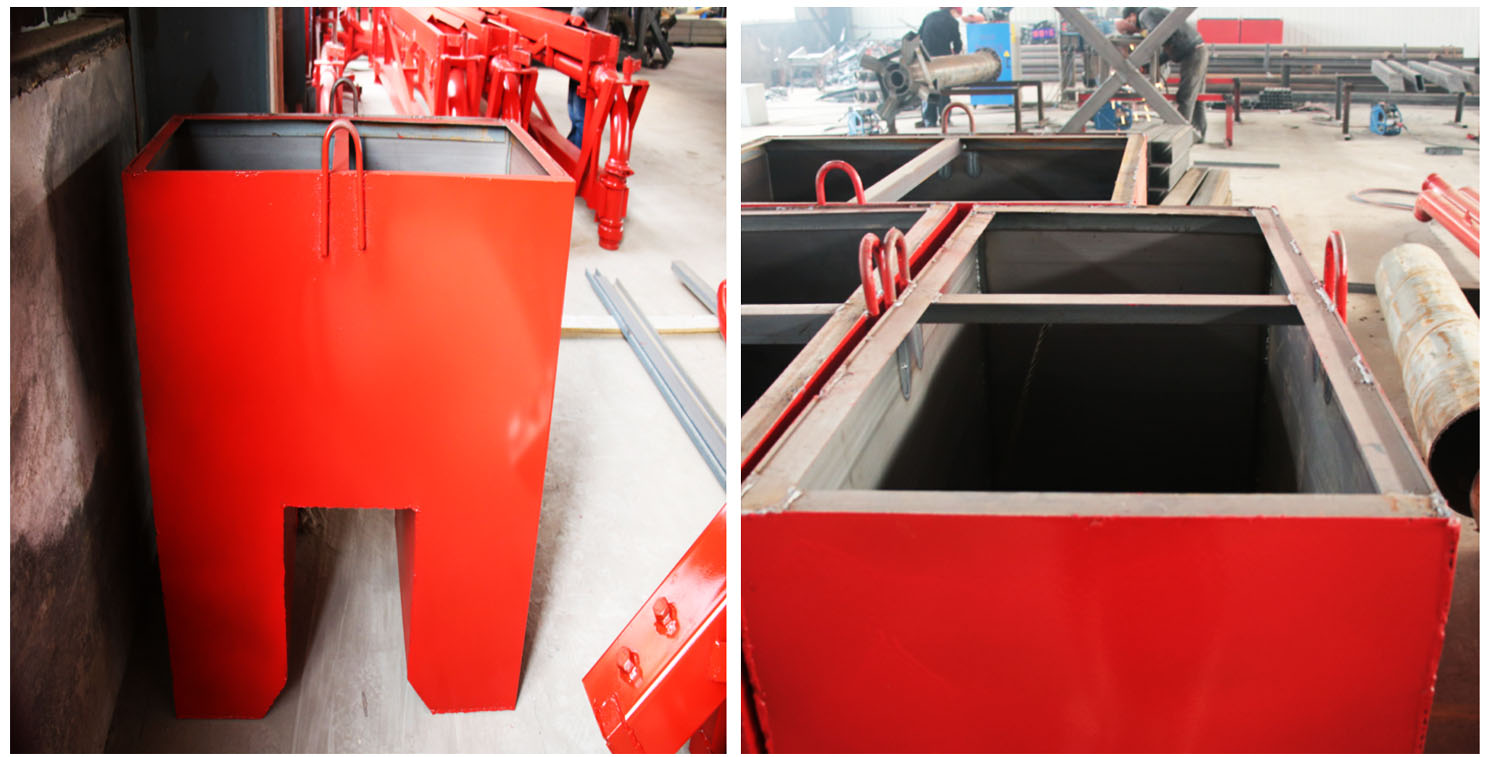
| The Balancer | / | 1 | pcs | |
| Vertical Pipe | DN125 | 1 | pcs | |
| End Hose | 2m | 1 | pcs | |
| 90° Elbow | 2 | pcs | Special used in concrete placing boom | |
| Straight Bearing | 1 | pcs | Fixed in the big arm | |
| Elbow Bearing | 90° R350 | 1 | pcs | Fixed in the big arm |
| Pull Rod | 2 | pcs | ||
| Leg | 4 | pcs | ||
| Clamp | DN125 | 4 | pcs | |
| Screw | 1 | pcs | ||
| Rope | 1 | pcs |
| 12m 15m 18m Concrete placing boom manually | |||
| Specifications | 12 meters manual | 15 meters manual | 18 meters manual |
| The big arm design | Dual channel | Dual channel | Dual channel |
| Radius of gyration (m) | 12 | 15 | 18 |
| The height of the placing boom | 4 | 4 | 4 |
| Diameter of conveying pipe (mm) | DN125 133*4.75mm | DN125 133*4.75mm | DN125 133*4.75mm |
| Leg span (m) | 3.2*3.2 | 4*4 | 4*4 |
| Rotation Methods | Manual | Manual | Manual |
| The whole weight (kg) | 1100 | 1500 | 1600 |
| With weight (kg) | 600 | 800 | 1000 |
| Slewing bearing type | 315 | 315 | 380 |
| Placing Area | 452m² | 700m² | 1017m² |
| Material | Square steel | Square steel | Square steel |
| Slewing range | 360° | 360° | 360° |

The Complete Machine (Manual Type)
IV The concrete placing boom parts detail pictures
Main beam frame:
The vertical stand:
The Balancer :
Elbow Bearing & Straight Bearing :
Four Legs :
V Pictures for Different type Concrete Placing Boom
Electric Concrete Placing Boom: (12m/15m/18m)
Different from the manual type, the electric placing boom has two electric engines. The other parts are almost similar with the manual type.
Elevator Concrete Placing Boom (Manual and Electric Type)
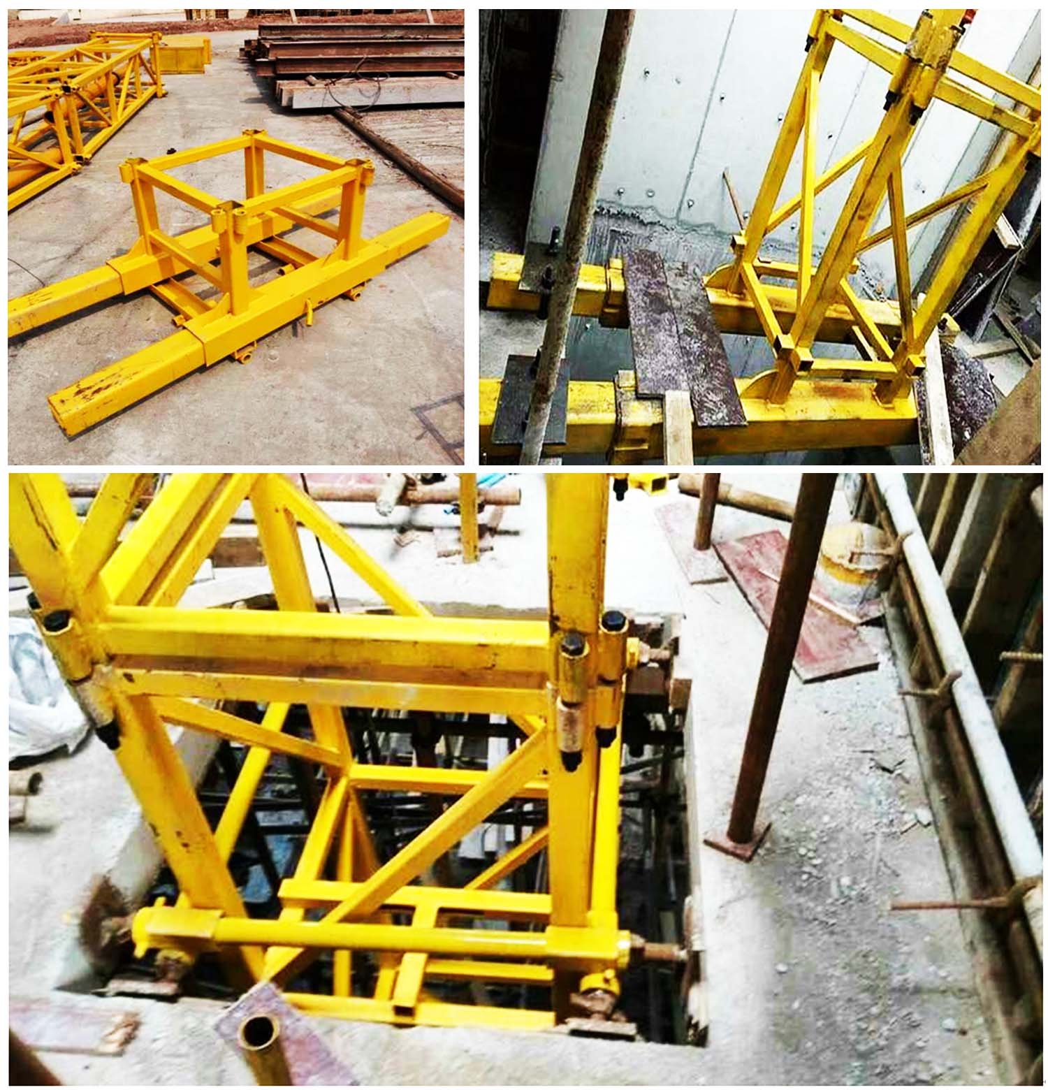
The most different parts of the elevator part is the vertical stand part. It is combined with three separate standard frame(3m per unit), so the standard pair for the placing boom is 9m. The down base is 0.7m and the up stand is 1m. So the total height is about 10.7m.
It must be installed in the elevator and the down base size would be designed by the customer’s construction site elevator. The drawing of the elevator sample is in the following part.
Elevator Concrete Placing Boom
